top of page
3D Match Moving
Today I learned about 3D match moving techniques, the nodes used for 3D, how the camera work in Nuke 3D space and navigating the 3D system.
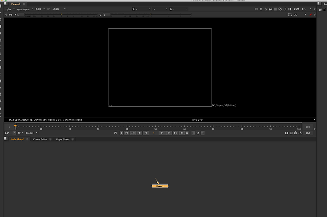
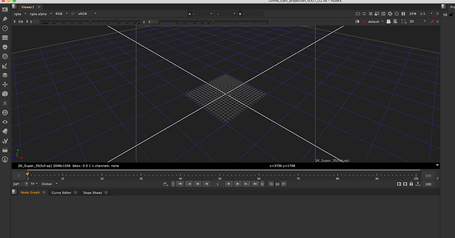
Pressing TAB changes scene from 2D to 3D.

Command + Shit - allows you to scale the 3D model.
By pressing Command you are able to rotate the model.
I created a cylinder and added colorbar to it.

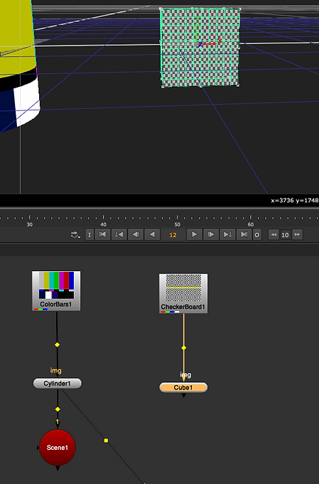
After creating a cube I added a checkerboard to it.

Red nodes are 3D nodes
I created a scene node to allow me to see my 3D elements on my 3D view
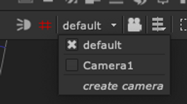
I added a camera so I could animate it al view the scene thought it.
This is how you change from default to camera view.

This are the different view ports in 3D

scanlineRender allows for 3D object to be viewed in 2D
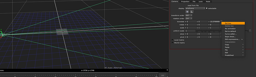

This is how a key is set.

Result of the simple animation.
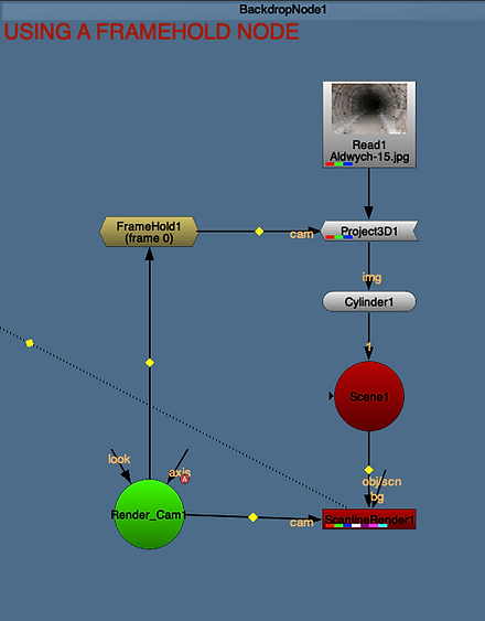
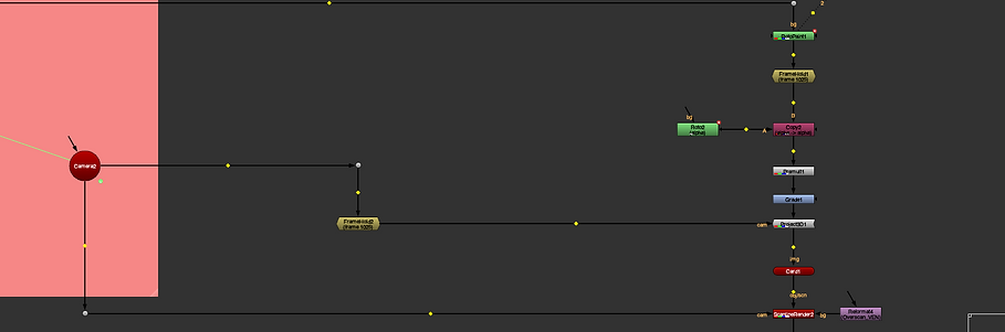
For this task I created the illusion that the camera was moving through the tunnel.
The nodes used were the Project3D, a cylinder, scene, hold and camera.
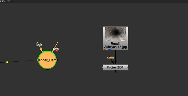
I added a Project3D node to put the image on a cylinder.

Add the cylinder under the Project 3D and a Scene node under the cylinder to view it in 3D.

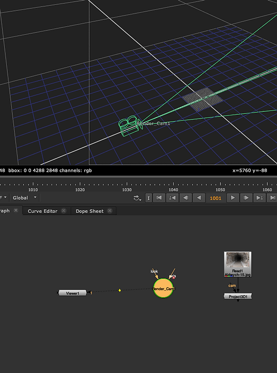
The ScanlineRender was used to view the image back in 2D.
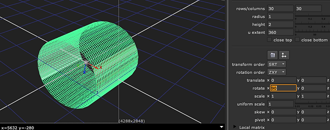
I rotate the cylinder.

Scaled the Y axis.


This was the result.
I fix this by setting a projection of the image by using a duplicated camera and taking away the default animation.


I tried a second method to achieve the same result.
I added a frame hold and connect it to the camera so it recognises the camera, then to the Project3D.
METHOD 1

METHOD 2
Result
For this task I was supposed to create a 3D cell using 2D images. I was not able to do it when I first tried it.

I brought the images.

Added a copy node a roto.
Used the roto nodes I created for all image to draw a roto around the parts I wanted to project.

Bluer was used for the edges.

Made sure that there was no clip on my roto nodes.
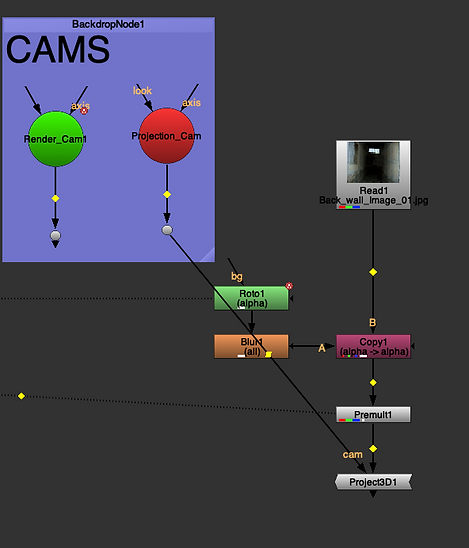
A premult was added to view the roto.
After that I added a Project3D and connected it to the projection camera.


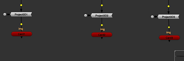
A card node was added to project the image.

I resized and adjusted the cards to fit the image.

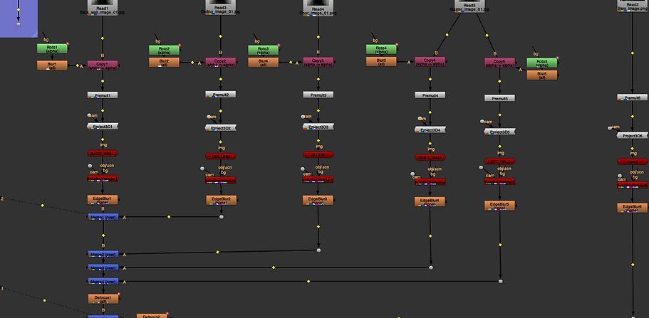
After adding the cards, I added scanlinerender nodes and connected them to the render camera(shift, select + Y connects node that are too far to drag.

Make sure crop is not selected.
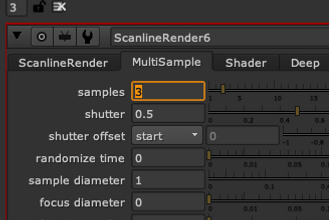
By adding samples in scanlinerender you can replicate motion bluer.


Defocus allowed me to create poor focus in certain frames.

Result
Here I learn about STMaps.
Old way.

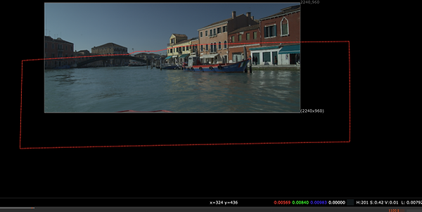
I used I grid to add a lens distortion to it(X+ LensDistortion).

By pressing analyze grid I undistorted the grid.


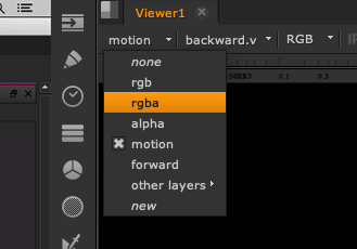
Changed the output type to displacement and viewed it through motion.

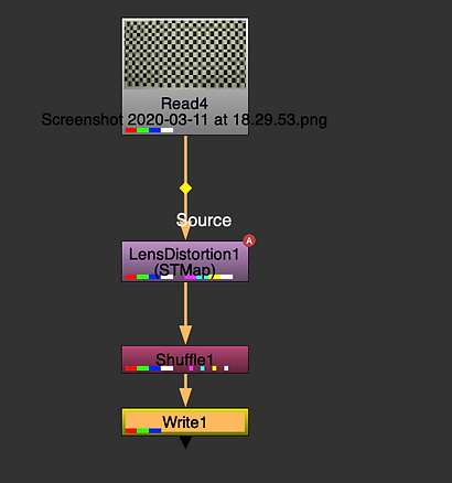
Added a shuffle node and changed the channel value to motion.


I changed the color space to linear , file type to exr and datatype to 32 bit for more information.
New way.
The process is the same.

Difference
Detect needs to be pressed to correct distortion.

Solve needs to be pressed and STMap mode needs to be selected.
Nuke 3D Tracking
I learned about 3D tracking and some of the problems that I can come across. The first thing to do is to track the markers placed around the scene then the camera will use the points information to create a 3D camera that replicates the movements. The more markers that a placed the better the information will be.


I brought in a camera tracker to be able to track my scene
Mask out the area to make sure the water will not be tracked (because the water is moving).

I used Roto to mask out above the water.

This is the result after the first track.

In the camera settings I have to change mask to source alpha


After tracking I had to delete the points that were rejected, then updated my solve. I repeated the same process until everything was solved.

I created a camera and camera point cloud base on the track I created
(under the camera tracker menu).
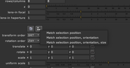
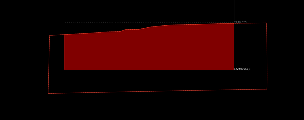
I selected two points in the scene then created a card and selected match selection position.

That put the card base on the selected vertex.
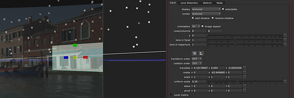
I then added a back-plate to the card.
The video shows the result.

I then held frame 1025 added a rotopaint and painted out the window.
a copy node and roto was added for the alpha and then premult allowed me to see the result.
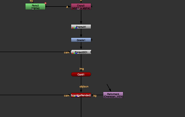
I then added the patch to the card by adding a project 3D under the premult and then connected to the camera.
The same frame hold was copied and added in between project 3D and the camera to make sure the projection holds.

I then connected a card to the projector and used the the process to put it in line with the point clouds.
ScanlineRender was added under the card and linked to the camera so I could view the patch in 2D and a copy of the reformat was to resize the patch.
The STmap was then connect to the ScanlineRender then everything was then merged back to the original footage.
Intro to XQuartz
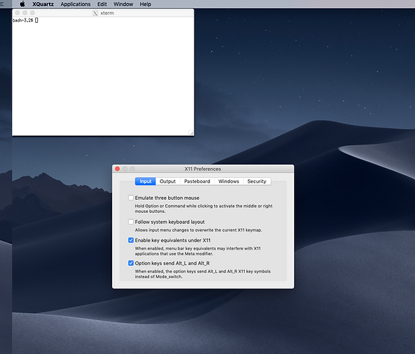
Make sure Option enable key and option key are on.
My Project/ Assessment 2
After setting the project I changed the way the scene look added my meshes, looked for the right position in the scene, adjusted the lights to get the effect I was looking for.

I created my Micro to add to the scene.
Here I smooth a square and used CV curve to create a few curves that I letter used to extract the faces.

Here you can see the faces extracted and the mesh smoothed.


Joints were created then properly oriented.


I parented the joints and bind the skin between the joints and mesh.
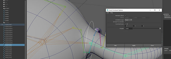
I created controls for each joints and then added a oriented constrain between each joints and curves.

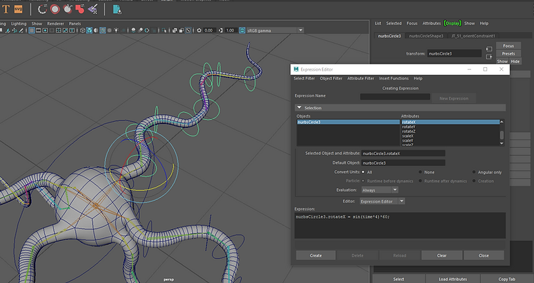
Here I created expression for the rotation of each axis.

Converted the polygons edges into curves and put it inside the mesh.

I then skinned the curves to the joint, to make sure it will follow the the animation created by the expression. ( I realize after , that without skinning the curves the were automatically following the mesh.

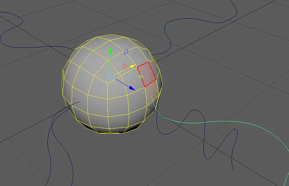
Here I created a sphere and added mash to it. They are being used to create lights going through the mesh.
A curve node was added.

In the mash curve menu I dragged and dropped the skinned curves.

I also inverted one of the curves and added to the menu.
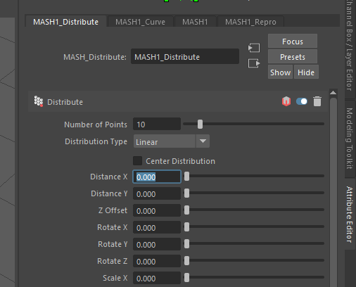
The distance x was changed to 0, resulting on every sphere created by the mesh being distribute properly.

Time node was added to added variations to the animation.

I then added a mesh light to the spheres and adjusted a few settings.
I aiStandardSurface shader was added to the mesh.
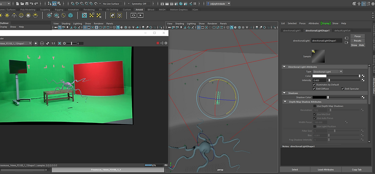
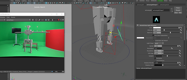
Here I am adding extra lights to the scene and adjusted it so the scene is well lit.

Here is a test render of the result.

Adjusting lights to make the shadow of my mesh more visible.
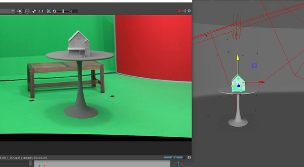
I modeled a table and added a house that I have created in another projects.
I used a model that I created for another project. Baked the animation and imported it in my scene.

I tried to add some reflection on the TV but was not successful. I will keep trying and update the new version when I find the solution.
FINAL RENDERS
bottom of page