top of page
Rigging and Creature FX
Introduction to Rigging
Rigging Overview - Tentacle
Today I used Maya to create a rig for a tentacle mesh.


I created a simple cube subdivided it, moved the axis to the button of the mesh (D-X-Middle mouse), froze the transform then the deleted history.

I added the soft selection to the mesh.


Created 4 joints.

Bind the skin, to connected the skeleton to the mesh.


Three primitives circles were created and used as main controls, then the joints become child's of the master control. The circles were positioned next to each joints then I froze their transform.


The second control become child of the first then a oriented constraint was added to the first control(select the curve then the joint).

This has to be on.

I added some animation to the rotation attribute by creating a new expression.

For the animation to work I had to add this code to the expression. depending on what number you added on the code, the speed can be changed around.
Result


Make sure that this is off.


After that a Mash Network was created. Mash allowed for time nodes and other nodes to be added to improve animation.


Distribution node allowed me to add multiple mesh.
Under distribute menu I change the type to mesh and then dragged the sphere to the input mesh to make the tentacle spreed around the sphere.
Grouped the circle and the tentacle mesh then added another mash to create multiple sphere with tentacles.

Test
Signal node creates a movement animation.
Joint Creation - ROBOT
Today I created some joints for a robot, created a test animation and added some effects to the robot.

Here I placed my joints along the axis with X selected to get them in a straight line.
If the joints are place all over maya will flip the axis and the rotation will not be consistent.

I turned on local rotation axis so I could see if I was snapping to the axis or close.

By selecting rot joint then holding V + middle mouse + small drag, I was able to snap to vertex.

When positioning the joints I had to switch from side and top view to position everything properly. I only moved the joint on X axis.

Had to make sure X axis was running down the joints.
Because it may cause problems when using IK handles and more.
X should be the primary asset.

I moved information from transform attributes rotation to the joint orient, and put the rotate axis to zero, to make sure the rotate attributes was free to animate.


I used the mirror joint options to mirror every joints created by searching for the name of the joint created and then replaced it with a new name.


Here I parent the joints with parts of the robot. By selecting the mesh then the joint I wanted to parent it to.


SKINNING - ARM
Today I skinned a mesh to joints by using bind skin and distribute the wight with paint skin wight tool.

I selected the mesh and joints then under the skin menu, then click on apply.

The joint was deselect to make sure I didn't accidentally press it.


By right clicking and selecting paint skin weights tool you will be able to use your tools to paint you mesh.

Inside the tool you can see the level of influence each joints have on the mesh.
Before skinning, a technical animation was created to see how the mesh reacted to movement.


To control what is being influence make sure to only unlock the ones that you want to be affected.

Here I went to select mode, select the wrist vertex then (ALT+right click+ grow) to grow the selection the (G) to repeat


I went into paint mode, replace , set the opacity to 1 and value to 1 then press flood to clean all the map out.
You can select deformed vertex go back to paint, select smooth then flood to fix the shape.
This can also be done by using the paint brush with smooth.
If the opacity is set to 0.1 you can add some wight to fix the shape.
(B) Resizes brush
Render

Rigging Controls Robot - MKII PT 01
Today I learned how to create rigging controls using Nerbs. That Allowed the robot to be controlled outside the joints and I was able to animated it thought the controls.

Here I created the nerb, snap to the joint, renamed it and froze the controls.

I added an attribute to the nerb, name it and set minimum to 0 and maximum to 1.


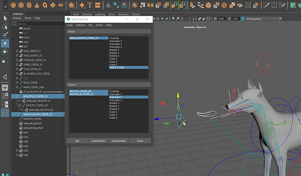
I open set driven key loaded the driver and selected the control under it. After that I selected the claw and press load driven


By having the driver , controls, the rotate axis selected I then created a key frame for each driven.
After keying I made sure that the claw control was set to one the I opened the driven and key framed again

Here I added a new attribute, changed the name and left everything else the same.


I added I code in the expression and changed the codes name to match mine.
The expression animated the wrist.

Render
Rigging Controls Robot - MKII PT 02

Snapped Nurbs to too the root joint

A different way of snapping is by selecting the thing you want to snap then where you want to snap it to, then pressing match translation.

Renamed the nurbs then frizzed the transform.

Constrain Root joint to root CNTRL.
By selecting the nurb, and shoot joint then under constrain I selected point.


I created custom atrributes to set driven keys control to control rotation. Selected my root control then added a new attribute

Renamed it and left everything else on default . Another attribute was created for left and right curl.
Then I was able to see it on extra attributes.


I can control the animation of one object by movement or change of a number of another.
I want control the rotation of the spines by changing the number on the extra attributes
To do that I need to set a driven key under the key menu(Animation).

In set driven key, you have a driver and if the number of the driver is changed will change the driven animation.
I selected root control and loaded it as the driver and my joints as the driven.


The same was done for the left and right controls the only difference was that rotate z was selected instead of Y.

I created another control to control the first root control.

Renamed it and frizzed the controls.

Under windows I click on the connection editor.


I selected the nurb and pressed reload left (or be having it selected before) and the same was done for the root control except for loading it on the right.
After that I selected the translate the what I wanted it to control.

I added a new controls and snapped it to the joint. Then named it and frizzed transform

I selected the control then the joints and then I opened the node editor


Visual representation of all the connections


I created a multiplyDivide and floatmath node, then I selected the SPINE_01_CNTRL and went into connection editor.


The multiply node was reloaded to the right side and, rotate x was selected for the CNTRL and input1X for multiplyDivide.
The output of x will feed into the input of the 1X


This was the result.


I changed the Input from 1 to -1 then reloaded floatmath to the right and multiplydivided to the left.


outputX and floatB was selected.


With JT_Spine rotate Y selected I reloaded it and feed its outputX to FloatB.

The out float of float math was then fed to the rotate Y.
Smiley

I created a cube then selected it and added a Mash to it.
Mash needs everything to be created in the middle.

A sphere was created then I scale it up covering some of the cubes.

In mash a changed the distribution type from liner to mesh.


The sphere was dragged and dropped in input mesh.


I put the number of points up and selected use face area so the cubes will be positioned properly.

A offset node was added and the scales were set to -0.8.

The sphere was hidden then a random node was added to the mash.


I made sure the position on random node was 0 and I also scale everything up.
A signal node was added.
That created an animation(the cubes started moving around).
The positions was set to one except from the Y , rotation to 360, scale to 2 and the time scale to 0.25 to make the movement a bit slower.

I brought in the mash menu for easier access to the menus.


Add color node and changed to black and another to yellow.

I created two spheres for eyes and one cube for the mouth. A nonlinear bend was used to bend the mouth to make a smile.


A fall object was created under the yellow color node.

The mesh was combines then dragged and dropped under falloff connection.

The falloff was then inverted. making the face black and body yellow.


I created a nurbscircle named it and changed degree to linear and sections to 4.
The control will be used to make smiley smile.

Had to change my orientation to world instead of object.
The axis was rotates with any object if the orientation is set to object.

I used set driven key to create a control for the smile.


After creating the controls for the smile I limited where the control goes.
HYDRAULICS

I selected each mesh and added a aim constrain to both.


Here I used the skeleton to control the mesh.
By selecting the skeleton then the mesh and adding a point constrain.


Here I created a helix and used its middle edge to create a curve. A curve tool was used to create the line in the middle.
Made sure to delete the history of everything on the scene.

I added wire to the mesh then the curve and did the same for the curve and line.

The number in the drop off distance has to be a high
number.

I was then able to stretch the helix around without it deforming.
PROJECT


For every joint, mesh or curves I placed in the scene I rename it and organized it accordingly.
I created the joints, rename it and move the value from the rotate attribute to joint orient. My rotation was even and free to animate.
When creating the joints I made sure to hold x to snap it to the grid and keep it in a straight line along the x axis.

I then mirror the joints and parent them properly (under the mirror menu I only changed the name and the position).
Parts of my legs were parented to the joint, the chest part and head.
I faced a few set backs because some of my rotation axis was facing the wrong way. I manage to solved the problem.

I skinned certain parts of the model that I wanted to twist.
Everything on the paint weights tools were locked expect from what I wanted to be affected.

Select mode + vertix select + Flood

Had to go back and parent the
the main mesh cntrl to the root
joint.


Made sure the limit how far some of my controls could move around.
I only named it and made sure everything else was set to default.
Driven keys were set and the information stayed in the attributes.
The drives controls the driven using their attributes.
Ex.(If the driver attribute is on -4 the driven attribute should be on this position rotation or other).
I then used connection editor to allow the second control to control the main one through translation axis.


OUTLINE of my controls and mesh.
Testing the controls.
MASH NETWORKS MOCAP

Added Mash to the cube and removed some cubes.

Set distribution type to grid so everything stay along the grid.

Changed distance between axis and grid.

Added a signal node to animate the cubes.
By changed the value of the steps in the signal attribute different the flow of animation changes.
ADDING COLOR


I just added the color node to add color, then choose the color and changed the hue and saturation level.
STRENGTH


I added a random node after deleting the signal node.

Played with the different strengths available to see what results I could get.


I added a strength map so I could have more controls of the strength.


I added a map help to the strength.


This map helper helps me control strength through scaling and translation.

Added a offset node and put the scale to -1.

Created a falloff, changed the shape to cube.

Set inner zone to 1.

Changed the falloff_offset scale from 10 to 1.

Scaled falloff to 5.

Put the inner zone down.

Changed offset Y position to 0.

Changed falloff shape to mesh.

Added a mesh to the falloff.

Changed the settings to achieve what I wanted.

Make sure Color Per Vertex is on(under Mesh repro )

Export Vertex Colors should be turned on (under Mash_ReproMeshShape)


To add color a new material needs to be applied to the mesh. Inside the color file you will find aiUserDataColor. The correct name should be entered.


You will find the color set editor under mesh display.

I added a mash to a sphere and put the x position down to 0.

I created a curve, added a curve node to the mash and dragged the curve under input curves.


Added a random node and changed Y and Z position. After that a signal node was added( I put the step amount down and changed z position.


Here I added a trail, put the scale up, created a curve and dragged it under profile curve to created a more define trail.


Here I changed from trails to join the dots to get a different effect.

I had to break the connection and re-add the curve for it to work properly.


Here I tried different effects to see what I could make.

I grouped the mesh's and curves. Saved the scene and imported it back in.


After that I changed the random position of the second mash, added a color node to it and dragged the new mash under the first mash's connection network.

I added Mash to a cube, changed distribution type to grid and added more distribution to X, Y and Z axis.

Added a transform node.

Changed the position and rotation.

Added dynamics.

Changed the collision margin, playback speed and bounce.


I created a constrain under dynamics.

I double click here to get to the constrain menu.

I played with different settings to get different results.

Fixing Mesh Scatter Noise

I added a Mash to a cube and dragged placed the mocap mesh into input Mesh.

Resized the cube.


Selected use face area the fix weird distortions.


Changed the starting point to -20. Selected all the joints and rotate, and added a zero to z axis.


Here I selected my mash, then created a mesh from mash points.


Here I selected the mesh created from points and my root joint.

I replaced the mocap mesh with the mesh created by points and changed the method to vertex.
Before
After
Mocap Dynamic


I added a color node to the mocap and played with the settings.

Added a dynamics node.

I played the animation and this was the first result.

Changed the ground to make sure everything falls in the right place.

Changed the bias position strength and rotational strength to delay the dynamics effect.

I created a falloff object for my dynamics.


Changed the Shape to cube and put the Inner zone up.
This was the result.

I scaled the fallout, re-positioned the falloff and inverted the falloff.

By putting the falloff to the maximum number the dynamics fell of completely.


I added and positioned a camera on the scene.

I played with the bounce to get the result I wanted.


I added a aiUserDataColor to the mesh and added the right name to the attribute inside color.

Had to make sure Export vertex color and color per vertex was on.


I exported the mesh selection to alembic. Made sure that the UV write and write color sets was turned on.


SPLINE IK

Spline IK makes movements more natural.
There is more movements than rotation in the spines of living things.


I created a IK spline by selecting the tool then the number of points I wanted, where I wanted the spline to start and end.

If the auto simplify curve is deselected , all the joints will have individual points for control.

By selecting Disp CV the curves points will be visible at all times.

A cluster was created to single and multiple points.

I created a circle curve then grouped it and duplicate the group four three times.
After renaming them I moved them next to my chosen joints( by parenting the curve to the joints then putting the translate to 0)


I used point constraint to make sure that every time I moved the curve the cluster would follow.
Individual joints were created for the tail then they were parented under the main joints.

I selected the mesh then the joints I wanted to pass the influence to.


Then the influence was added.

Had to make sure that only the root joint and the spine was unlocked before I added a influence.
Adding meshes as influence


Created a sphere parented under the shoulder joints and them position it where I wanted.
Selected the mesh then the sphere and added the influence.
I locked everything except from the shoulder and the sphere.
I then selected add paint the put the value to 0.1.
I then set driven keys. The elbow joint was the driver and the sphere the driven. I also selected what attribute of the drive was going to affect the chosen driven attributes.
BLEND-SHAPES

I created one plane, duplicated it 2 times and named them.
Soft selection was used to create the hill and valley .


This is the result.
Both shapes that will be used to blend the shapes are selected first then the base shape .
Under deform we select blend shape them create.

The base shape will change if you move the sliders up or down(+ or -)

Problems

Here I turn display vertices and component vertices on so I could see the numbers of points my mesh has.
For the blend shape to work, the base and the shape that will be used to blend should be the same from the start.

I deleted some faces and reconstruct it. That created vertices with different number.
Because some numbers did not much the result was not good.
Limitations

Duplicated a faces on the sphere and rotate it to the opposite side.

I added a blend shape to the faces and created a polygon to see how the faces were moving.


Blend shapes are liner deforms.
So before using it we need to make sure that it will not interfere with what we want to do.
BLEND-SHAPES SHAPE EDITOR

I changed the workspace to Pose Sculpting.

I selected the mesh then created a blend-shape.

Then added a target under the mesh.


With edit on I manipulated the vertices to created a smile, then turned it off.
When the slider moved the mouth follows.
I Duplicated the target and flip it to the other corner of the mouth.
Result

Here I added a combination target, that allows me to add another layer of sculpture driven by the blend shapes.

The values of the target will change when I move the blend shapes.

I used the grab sculpture tool to add some more detail to my smile.

Symmetry was turn on before I started sculpting.
POSE EDITOR

Created a Blend shape so I could have a base shape I could go back to.

I created a pose interpolator and with the joints I wanted to be the drivers selected, I added a pose and named it mouth open.

I used the joints to open the mouth with pose on edit then I updated the pose once edit was turned off.
Used channel box to rotate.

By right clicking and selecting pose you will go to the available pose.

The sculpture tool was used to defined the smile with target selected and edit on.
MOUTH RIG CONTROLLERS

I created two nurbs circles to use as controls for the mouth.

I added IK handle to each joints. Made sure that single-chain solver was selected.


BLENDSHAPES CONTROLS POSE EDITOR
Each IK handle was parented under their controllers.
After that the sub control was parented under the main one and I was able to use the nurbs to control the mouth movement on translate.

Here I added a new pose and used my controls to edit the pose, by moving the controls to -1.

Changed the pose attribute from default to advance. To add controls to drive poses and blendshapes.

I pressed add, turn the attributes channels on and moved the translate of each controls to there specific place.


Had to delete my neutral pose and add it again because when I pressed to pose on neutral everything stayed the same.
Here I just adjusted the pose to get a better smile.

The controls were working just fine.
BLENDSHAPES EYE LID

Added a blendshape to the eye lid mesh and created another to add a target to it.


Selected the points I wanted to move to close the lid.

Turned on soft selection and change mode to surface.


Changed the position of my axis then rotated the lid.
Made sure that that edit was on for my target.


I repeated the same
process for the second lid.
To make the eye lid closing more realistic a in-between target was added at 0.650 to delay the deformation of the second lid. Gives you more control over the deformation.
I then used a target eraser to take my lower eye lid to the start position so it could only start from the set number.
SUB PIVOT CONTROLS - SQUASH AND STRETCH

I added a IK handle to the joints.

I then parented it under a nurbs created to control the leg.

Two more IK's were added to allow control over the ankle and toe(current solver was changed to single-chain solver).


Here I grouped the toe IK and moved the group pivot point.

Grouped the ankle and foot IK changed the pivot point and also created a group a main group where everything can be controlled from.(The pivot point was also moved under the ankle joint.


I created to more groups and changed the pivot point to the toe and angle joint.
Testing the groups.
STRETCH SQUASH

I created four spheres added spline joints to them.


I them parented each sphere to the right joints.

Here I duplicated the joints, then kept the top and bottom joint.

Each joint was then skinned to the IK handles nurbs curve.

Max influences was set to 2 because there's only two joints to influence.


Here I created two controls for each joints.

Parented the joints under the controls.
Heading 6


I selected the vertex on the curve, then changed the skin influence of the points in the middle.


Added a curveinfo and linked it to a IK curves shapes (not orig). This allowed me to find out the length of the IK handle.

I added a multiply and divide node and linked the arch length to it's input 1X.

This allows me to multiply, divide and more. I changed the operation to divide so, every time the input 1 number changed (the original length), then it would be divided by the original number on input 2.

I then connected the input (1X) to the joints scale (X)
The joints were dragged and dropped on the node editor.
This allows for the spheres to stretch but the proportion was lost.

I added another multiply and divide node and changed the operation to power and the input 1 to 1.00 and 2 to 0.500.

Another multiply & divide was added and the operation was changed to divide (Input 1/ 1.00 and Input 2/ 1.00
The result of the power calculation was divide by one.


I then connected the output of X to scale of Y and Z of every joint.
This allowed the proportion of the sphere to be consistent.

Added a IK handle to my joints and created a control for it.

Added a point constrain between the IK handle and the control.


Then measure the distance between the joints.

I parented one locator under the shoulder joints and another under the IK handle control.

Added a new attribute under the control.

Used the attribute to create an expression.

I added a script to the expression that allowed my arm to stretch if the distance is greater or equal to 6.123759 then my scale is equal to the distance divided by 6.123759.


ALIEN MESH FUR

Here I used automatic UV to layout my mesh.

Used a motion capture from content browser for a small animation.

Created a quick rig for my
mesh.
Used perfect mesh.

Adjusted the position of some points.
After that I created skeleton and control rig and skinned everything.

Here a added quickrig to character and the motion capture to source.

Changed the workspace to interactive groom.

Here I selected the mesh and created a interactive groom splines.
Changed the settings to affect the length of the hair.


Adjusted the taper and taper start.

Put the density up just to see how it looked.

Create a map for my mask.


Masked out the parts I did not want the hair to be.


Saved my UV so I could use it on Photoshop and did the same to my mask map.

Added a levels adjustment layer.

Duplicated my mask map layer and with the first masked map layer selected I selected parts of the map by pressing (ALT+ DELETE). That created a black stamp around the map.


Painted parts of the UV.


Saved everything with IFF format.

Turned of the UV layer.

After updating the map the hairs of the hands, feet and head completely disappear.

Added a guide to the editor.

With guide selected I pressed create to guides to create the furs.

I put the density multiplier to 5.

Matched the primitive attributes to the xgemSpline.

Adjusted the size of the fur.
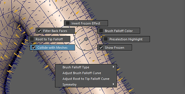
Made sure the collide with meshes was on. I also turned on the symmetry on.

Added sculpt layers for each interactive grooming tools I used. Changed the collision distance.


I added a clump to the editor and put the density up.

I connected the guide shape outSpline with the clump input points.


Turned this options on to update the information of the connections done in the node editor. Played with clump effects and clump scale to get the effects I wanted.

Added another clump and changed some of the settings.
Heading 6

Added a hairshader.

After adding a color picture to the mask map I put it in the color base of my hairshader.

I added a shader to the mesh and added other texture under the base color.


I added the same texture to the layeredtexture1 and then connected it the out color R from the mask map to the Alpha layeredtexture1 to make sure that only the unmasked parts were affected.

I adjusted the transmission and some other settings to get the look I wanted.

Here I put up the Specular, Camera and SSS.

I created I cache for my fur for the frames I wanted.


I connected the emission to the out color of the fur.

ASSESSMENT 2
Organic Rig

Here I created my joints, then skinned them to my mesh .

I mainly used the select
vertex option to to skin most
of my dog.
(by selecting what I wanted to be affected and flooding it.


In the later stages of my project I came across some weights problem, because of the high amount of history my mesh had.
After deleting the history the weight was back, but because I made changes to the mesh after the weight was applied, some of the weights were not spread properly.
I had to paint the weight again. This time I made sure to have it saved in a different file. There was no more changes done to the mesh.

Here I added a IK spline handle to the spine of the dog.


I then added clusters so the curves of the spline handle could be controlled.
I also created a few curves and placed them around the joints I wanted to control.

Each curves had their own group. A point constrain was a added between the spline curves and clusters so I could control the clusters using the curves.

Each group was put under a curve.So I could move it as a group or individually.


Here I added a new control for the leg by using a curve to control IK handles.

For the second IK I only used a single-chain solver.

Here I put both IK's under the nurbs then grouped one of them and changed the position of the pivot point.
I also grouped the new group with another IK handle and changed the position of pivot.
Each group will be used to control different leg movements.

Here I created a attributes for the my main control.

I created a connection between the nurbs, twist and rotate groups.

I had to go back and do this process again after painting the weight on my mesh.

Here I added a spline IK to the tails joints.
Added clusters to the Ik curve and created individual curve controls to control the clusters.
They were each under a group.
I then parent each group under a curve control.

I created a main control then added a attribute to it.
The attribute was then used to control the small controllers through the set driven keys.

The connection editor was then used to control the main control using translate x, through another controller.

After adding joints to the tongue mesh, a IK spline was added.
The top and base joints were duplicated and then a bind skin was added between them and the curve created by the IK spline. That resulted on the points of the curve moving when the top or base cntrl was moved.
In this screenshot I am changing the number of two different points on the curve to distribute their weights properly.

I added the Ik spline curve to the node editor and connected it to a curve info to find out the length of the curve.

A multiply and divide node was added. The operation was changed to divide. The input 2 number was changed to the length of the curve.
If the length of the curve changes then it would be dived by the original length.

I then connected the output x to the scale x.
This allowed the tongue to stretch.

Another multiplydivide was added. The operation changed to power. The input 2 was changed to 0.500.
The original length of the curve dived by whatever number the curve length is.(Because the curve is not moved the number is one).
(1 to the power of 0.500)

The result in then dived by the same number.

The output was then connected to both y and z scale.
This allowed the tongue to stretch and shrink with the proper proportion.

I added blendshapes to my hears, eyes and mouth.
To create a blend shape. First I selected the mesh then clicked on create blend-shape. To edit it I added a target to the blend shape.


For the eyes and ears I duplicated the target, then flipped the target.


To created a blend shape for the mouth I selected 2 joints that I wanted to blend the shape through.


Here I created a new pose and edit it.

The pose was then updated.

To control the blend shapes added to the joints I added a Ik handle with single chain solver.


After creating controls for the blend shape.

I turned on attributes (channel

Dragged and dropped the translate of the controllers on the right driver.

I then parented each Ik handle to the correct control and parented the second control under the first one.
I then created a main control and set a driven key. So I could control the first and second controller through the a attribute. Another control was then use to control the main through translate Y.
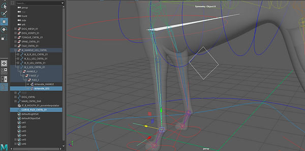
Here I added a extra control for my legs flex by selecting the IK then the control and adding a pole vecrtor.

Testing of controls


I was not able to complete my walk cycle.
The animation was done for the body head and back legs.
I did not test how far the forward legs reached because of that when I started animating it the animation did not look right.
I tried to add stretch to it, but it did not solve the problem.
I used xgen but was not able to put fur or the dog properly.
Overall I learn more techniques about rigging.
Had a few problems that I now know how to solve.
Found it difficult to use Xgen but I will keep practicing.
Very good learning experience.
Mash Experiment

I modeled a simple cube with two different faces them added Mash to it.
Above you can see the the settings I changed to get the result you see in the image.

I added a offset and only change the rotation to 180 on 1 axis.

Created a falloff for the offset.

Changed a few settings.

Added a color node to the mash.

And by dragging the offset falloff then pressing alt and dropping it in the color falloff I was able to clone the falloff. (same settings but used for different functions)

I imported the mash into the node graph.

Removed some of the nodes that were not necessary for this test.
By duplicating the offset on the outliner then dragging and dropping it in the color node falloff I could also clone the it.

to make sure the color reacted to the position on the cubes I used the same falloff to control both nodes.

Here I put the scale off the falloff of set down so I could animate it from begging to end.

Set keys on the scale on low and high on different frames


Added a spring node to get a little bounce and anticked the scale on the spring.

I set the scene, added some lights.

Added a new material to the mesh and added a AiUserData color to the emission (under display I check on color set editor to see what name I had to put under my AiUserData color to get my colors to be visible in arnold render).
The export Vertex Colors and color per vertex had to be on to make sure the colors appeared.

I just changed the base color and background colour of the mash.

Result
Similar Process
Performance Animation
Experimenting with Mash
bottom of page